Rover 2 SpyTank Teardown
Brookstone Rover 2.0 SpyTank Teardown

- Brookstone SpyTank
The Brookstone SpyTank is a track-driven spy cam with night vision that you can remote control using a tablet computer. It includes auditory listening and loudspeaker functionality in its arsenal of intelligence gathering weaponry. Drive it around to surveil targets, gather intelligence, and master your environment. Your home may never be the same.
While the SpyTank provides an initial high level of fun for a wide range of users, it tends to lose its appeal fairly quickly. It’s one of those toys that is relegated to the closet shortly after its first set of batteries die.
There are other reasons to buy the SpyTank, however. Embedded Systems Designers will quickly realize that the SpyTank is a networkable, mobile, embedded computer with a cool camera. For $150, it packs a big technology punch. You would be very hard-pressed to put together a similar platform from off-the-shelf components for the same price. It’s probably running Linux. And hey – it just looks cool.
Product Review
In OE (Original Equipment) trim, the SpyTank worked well with an iPad tablet. While it was controllable using a Kindle Fire HD and a Nexus 7 running Jelly Bean, video was not available on either Android platform. Your mileage may vary with other Android tablets.
Controlling the tank using the app and live video feed alone is a little tricky as there is a perceivable delay between what you see on the tablet and real life. You have to think ahead to avoid repeatedly smacking into obstacles. The trickiness of the left and right track controls adds to the challenge. With a little practice, you can make the tank stumble around where you want, but a steering wheel and forward/backward joystick would probably be more effective. The experience of driving a tank may be part of the novelty to this little device, but the lack of control tactility is a limiting factor.
Teardown
Not only would “hacking” this platform be a good learning experience for those wishing to design similar technology, we may be able to make it function better. While the SpyTank possesses a lot of potential as a development platform, the verdict is still out how easily it can be modified. Follow along for some pictures of the SpyTank internals to get some ideas how you may use it for your own projects. Maybe you can take it to the next level? I’ll include some hints as to what that might entail.
The chassis comes apart very easily. Simply remove all screws from the bottom of the tank and it will split in two main sections. There aren’t even any hidden screws under stickers for tamper evidence. Several sets of wires connect the two halves. Unplug the necessary wires using the connectors for further disassembly. All connectors have unique shapes and colors, so putting everything back together without making mistakes is relatively simple.

Top and Bottom Halves

Top and Bottom Side-By-Side
The top of the SpyTank holds the motorized camera turret, the Wifi module, antenna connector, a speaker for audio transmission, and the “status” LED.

Tank Top
The bottom of the SpyTank contains a drive-train, reset button, power LED, battery holder, park lights, and the main controller board. Everything is connected to the controller board using connectors, which makes it easier to work on. The tracks do not have to be removed, but they are easy to pull on and off.

Tank Bottom
The drive-train consists of a motor and gearbox in the back for the rear wheel and an idler wheel on the front. A spring-loaded slide mechanism on the idler wheel keeps the rubberized tracks taught between each set of two wheels. The idler wheel somewhat floats up and down because of the way the slide mechanism is connected to the chassis. This floating action and the spring combine to provide a suspension for the tank as well. Multitasking the spring like this is ingenious design; intended or not.

Front Suspension
The motor and gearbox are modular and look very easy to reuse.

Rear Motor and Gearbox
Shown below is the top of the control board. It includes an anonymous CPU/SOC (System On Chip) with no markings on the 128 pin TQFP, a Winbond SDRAM chip, a ULN2803, four ME4542 ICs, two FP6188 ICs, a GPY0030B chip, an unknown IC labeled RC816, and an F84KYZZ IC. Datasheets for the parts are shown below along with links.

Top of Control Board
The bottom of the control board features a flash chip and a few discrete components. Looking at silk-screened labels on a PCB can often provide useful information.

Bottom of Control Board
We learn the location of a potential serial port which may aid in hacking the device. These pins run down to a daughterboard on the bottom of the tank chassis.

UART Location
The motor for the camera allows users to point it up and down within the turret. Judging from the number of wires, it looks like a stepper motor.
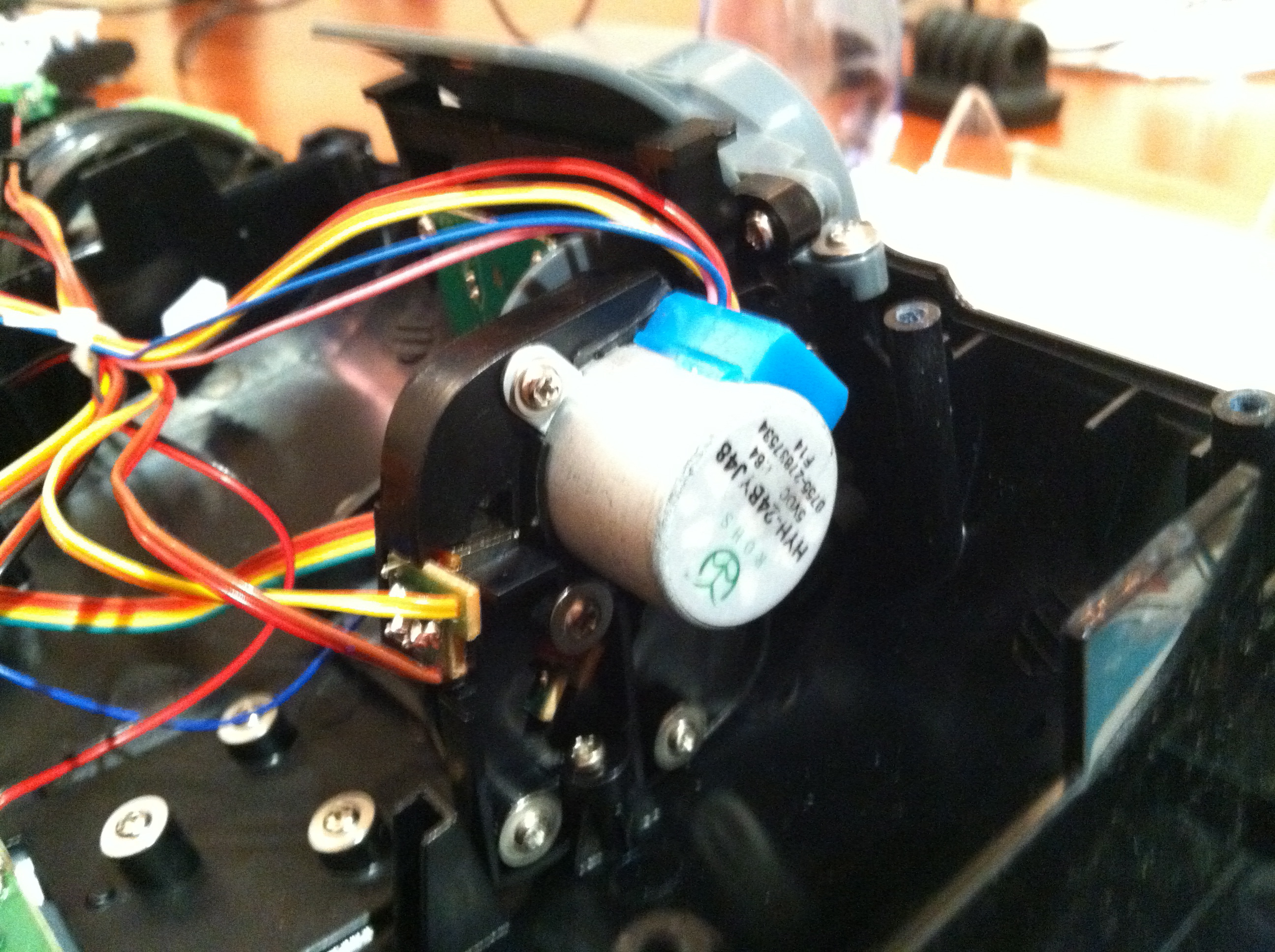
Motor for camera
A shot of the camera module itself.

Camera Module
The Wifi module links to the control board with four wires. If you’re thinking USB, you’re probably right. The markings on it are BL-RT3070-U2.

Wifi Module
Datasheets
- RAM: Winbond SDRAM
- ROM: S29GL032N
- CPU: 128 pin TQFP – no discernable labeling or markings
- RT3070 based Wifi module
- H-Bridge: ME4542
- Buck Regulator: FP6188
- Audio Driver: GPY0030B
- Stepper Motor Driver: ULN2803
- Unknown IC: RC816
- Unknown IC: F84KYZZ
How It Works
The main drive motors are controlled by two H-Bridge circuits, which are made up of the ME4542 MOSFET ICs. They’re probably switched by GPIO signals from the CPU and provide skid steer by allowing independent forward and backward commands on each side.
The ULN2803 is likely used as a stepper motor driver for the turret control motor. It’s not a regular servo motor. A limit switch allows the CPU to determine when the camera is pointing all the way up (or down maybe). The user can move the turret in small “steps” with easy software control of the stepper motor. It’s a simple and effective design.
The FP6188 chips provide voltage regulation for the device. They convert the voltage the batteries provide into levels more palatable to the ICs and other circuitry. They may provide power for motors, but it’s likely that the motors connect directly to the batteries.
The GPY0030B is an audio driver IC. It’s likely used for the loudspeaker. Users can send their voice from a controlling tablet to the tank for others to hear.
A mic is also included in the camera turret. I’m not sure how that circuitry works. There are a couple other ICs that may do the job. I couldn’t locate datasheets for them.
The camera and Wifi module are probably connected via USB to the SOC. The OS (Operating System) contains software to make them work. Commands and audio are sent from the tablet to the tank, and video and audio are sent from the tank to the tablet.
Next Steps
The system is probably running Linux. It takes a while to become ready after the power switch is turned on, which is typical of Linux. A smaller RTOS would likely come up much faster. The fact that the device requires networking, and streaming of sound and video also lends itself to a Linux system. Linux already includes much of the software to make everything work. The size of the RAM and Flash suggest a lean, but very workable Linux based system.
My guess is the CPU contains an ARM core. Maybe it’s an Atmel ARM based CPU, for example? Determining what CPU/SOC the SpyTank contains is a big part of making it highly customizable. It is likely a lot can be done using the software already on the device, though.
The flash could be desoldered and probably socketed with relative ease. This would allow hackers to examine the system’s root filesystem. Doing this would tell us the instruction set of the SOC, and provide a list of software that’s on the system. Modifications could be made to the system by reflashing the ROM with a programmer. If the flash was socketed making changes becomes a fairly easy proposition. Once a way into the system is established this method quickly becomes too slow, and faster ways to make changes become available.
The Wifi and camera are probably connected as USB devices. Other devices like thumb-drives or ethernet bridges could be connected in their place. The existing Wifi can probably be used for NFS or SSHFS mounts for quicker development.
A simple network probe for all open ports on the device might turn something interesting up. Check out the nmap tool and hit it from your computer once associated to the device’s Wifi network.
One thing to commonly look for on an embedded system is a serial port. The serial port is often used for console access. It may not even require a password.
I mentioned a daughterboard on the bottom of the tank’s chassis earlier in the article. That board exposes a reset switch and a connector for the serial port. By removing two plates, the serial port pins are exposed for easy connection. These pins are likely only 5V or 3.3V tolerant, so don’t connect a regular RS232 port to them. You’ll probably need to get a level converter or special cable. Take a look at the signals on a scope to get a hint.
Miscellaneous Diagrams
Shown here is the serial port access door. Remove the larger door first by removing the screw, then remove the smaller cover by prying it from its hole. The pins are GND, RX, TX from left to right in the picture below.

Serial Port Access
Here’s a listing of the connectors. The “turret limit” connector probably also contains the mic signals.

Connector map

Have Fun
I may explore this system a little more in the future if I can find time. It looks pretty easy to work with. I initially scoured the net looking for a teardown on this little device, but couldn’t find anything. Oddly enough, when I was searching part numbers for the Wifi unit, I came up with an AC13 Brookstone Rover article with a lot of great data. It’s an older version of the same toy, but they look very similar.
Let me know if you find anything new about the SpyTank. I will include updates here if I make any future progress. Most of all – have fun!

_If_ it contains linux, then you are entitled for its sources (under GPL). So search vendor website and ask for sources… you’ll learn great deal about the system that way.
Good point – I like the way you think. 🙂 Check the AC13 Brookstone Rover article link in the second to last paragraph. It is Linux.
FWIW, GPL mandates publishing source for anything that’s statically linked to GPL code, but there are still plenty of ways to keep Intellectual Property secret with standalone programs, libraries and kernel modules.
Do you think you could take the circuit board, camera, and wifi, and put them on a helicopter-style drone?
You probably could. Personally I’d just buy something that was already setup as a drone – probably much cheaper. I think some of the toy drones out there even have SDKs for customizable control.
‘surveil’ is NOT a verb…surveiller IS a French verb. In English try ‘watch’, ‘look at’, ‘spy on’…
http://www.merriam-webster.com/dictionary/surveil
First Known Use: 1914
BTW – I was not paid to write this blog. That said, donations gratefully accepted. 🙂
‘nmap’ is a program that can run network scans from your computer / tablet that may tell you what OS and version is hosting the device as well as available ports, etc.
http://en.wikipedia.org/wiki/Nmap
The solder points shown on the lower left corner of the “UART location” shot is almost certainly a USB port: GND, D+, D-, +5V. It wouldn’t hurt to wire it up to a USB cable and plug it in to a PC.
Oops, lower *right*…
You’re probably right about it being USB. That’s the camera port. It’s a bit tricky, but you can correlate it to the labels in the second from last pic – the one that diagrams most of the port locations.
Based on the board markings my money is on a Nuvoton (Winbond) NUC745A, and 80MHz ARM7
IPCAM and W90P745 would be good Google related terms.
1J2 is a USB connection, silk screen marks GND, 5V, DP0, DM0 on the reverse.
The serial connector F-RST, GND, TXD0, RXD0
JTAG might exist via test points, would need to probe wrt to 745 pin out.
Might expect a boot loader message at 115200 8N1
Click to access Nuvoton%20W90N745%20-%20W90N745%20Bootloader%20Users%20Manual.pdf
http://html.alldatasheet.com/html-pdf/218660/WINBOND/W90N745CDG/297/1/W90N745CDG.html
Click to access W90N745CDG.pdf
Click to access W90N745-uClinux-BSP-User-Manual.pdf
Good stuff. Thanks. You’re making it difficult to stop digging for info. 😉
In case you missed the link above, check http://www.openipcam.com/forum/index.php/topic,261.0.html for lots of good detail on the first Rover. They look very similar.
Nmap shows port 80 is the only open port on Rover 2.0 as well. Haven’t tried hooking up a serial port yet, but it’s very simple once I dig out my adapter.
Control the thing with simple CGI commands found here:
http://www.openipcam.com/forum/index.php/topic,45.0.html
one of those unknown IC’s sound like a samsung 8bit micro, S3F84K4 maybe?
Link to Samsung S3F84K4 Datasheet:-
Click to access um_s3f84k4_rev10.pdf
That 128 pin chip is probably more likely to be an FPGA – either a Xilinx Spartan or an Altera Cyclone. Probably it’s running a firmware image that makes it into an SoC. If it was a BGA chip then I’d start to suspect an ARM SoC – but this package with the pins around the edge is less common for those. I’d look for a little SPI eeprom chip, and whether the pins it’s attached to match up with the 128 pin version of either of the above couple chips. Then I’d check to see whether the ground/power connections are right also. Is there a JTAG port? It’d look like an unpopulated header, probably 6 pins or so.
If it’s an FPGA, then it’s just more hackable. Otherwise, if no little SPI eeprom, it might be a “hardcopy” chip – it was an FPGA while the design was being finalized, but for production they may have had the firmware changed to become hardware – no longer reconfigurable.
These FPGA chips are popular for this sort of thing – it becomes easy to do a lot of “glue” logic to handle things like image sensors and sound and motor controllers. And yes, you can run linux on them.
I just got one of these and although it works well, the wii cuts out about 2 minutes into use. I have tried it out on both my iPhone 3s and an iPad retna. I can reconnect by going through the settings again but it’s just not acceptable. Any
I wanted to say “wifi”. Not “wii”
Never mind. The batteries were low and that’s why the wifi was dropping.
I have to say this is a very well written article. I purchased a happy cow ispy tank and am looking to upgrade it. do you know the tanks web interface password? it appears as a htaccess login box when accessed via a browser while connected to its wireless netowork.
are you available for discussion on this? it seems you may have more knowledge then others i have found
many thanks
robert
Check the forum link toward the end of the article for the original rover. They have some good info there. I haven’t had time to hack much more on this project.
hi Robert,
I am interested in chatting to you about the HC tank? To access the web interface,
http://10.10.1.1 into browser. U/P == HAPPYCOW/HAPPYCOW
What else have you learned about it?
First of all, thank you for these information. I want to know if there is any information about drive motor working voltage range and rpm ?? I am going to use this product and I need to control speed of motors by using PWM.
This is the same chassis (and some of the same electronics) as the SpyGear Spy Trakr.
I was thinking about buying one of these, but I am very concerned that you could not get video on either Android devices you tried. Without video, this spytank would be far, far less fun.
Has anyone been able to see “live” video when using the Android (Google Play) app?
http://home.wlu.edu/~levys/software/roverpylot/
Is there any chance to get the rover work behind internet connection? The IOS app is made to work on a ad-hoc wifi connection, I wonder if is that the only way to control the unit…
The rover creates an Access Point you must connect to with Wifi. If you bridged a connection to the Rover AP to your LAN and then punched a hole through your firewall (hopefully you have one) it would be possible, but it’s going to require some moderate know-how.
It looks like gaining console access via the serial port is very easy using a TTL USB serial cable based on this post from Simon Levy at the IS Group:
http://isgroupblog.blogspot.com/2013/09/how-i-hacked-brookstone-rover-20.html
He was able to browse some of the filesystem (not sure if it was root.)
Has anyone had any luck finding the source code and/or exposing the software from the console?
Serial console is as simple as connecting a 3.3V serial port. Getting binaries off requires some work from the bootloader. There were some users using Python to convert ascii dumps from the bootloader to files. Didn’t find the time to ask for a copy.
The shell is so limited I couldn’t see an easy way to get binaries off the box any other way. The developers did a great job stripping things down.
I want to build some gps related hardware features on top of this device.
Can you help with this or help me find someone who can?
I have seen information that this is a modified FOSCAM PTZ that uses the PTZ commands for the control. Anyone know which FOZ it is maybe the real control can be had by flashing this with new FOSCAM firmware or web interface BINS.
I’m looking into purchasing a rover that has video and that I can control over the internet using a smartphone or computer. The Brookstone looks like a good candidate BUT I haven’t come across any mods/hacks yet. Can anyone confirm this has been done? Any links, or alternative rovers? Thank you!
So I was wondering if the tank could handle 14500’s
Does any body knows the specifications of the antenna? I need to buy a new one (a friend of mine lost the original) but I dont know wich antenna is it.. tnx (sry bad english)